Orifice Flow Calculator
Use the orifice equation to find the flow through an orifice, its pressure drop, or the orifice size for a target flow, with or without a pipe upstream.
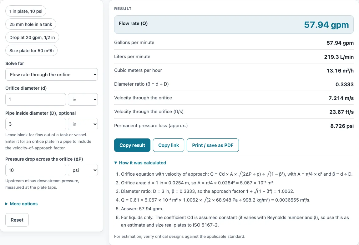
How to use the Orifice Flow Calculator
- Under Solve for, pick: flow from orifice diameter and pressure drop, pressure drop from diameter and flow, or orifice diameter from flow and pressure drop.
- Enter the known values. Each quantity has its own unit menu. Diameters can be in in, mm or cm, pressure drop in psi, bar, kPa or Pa, and flow in gpm, L/min, m3/h or L/s.
- If the orifice sits in a pipe, enter the pipe inside diameter. Leave it blank if the liquid discharges freely from a tank or vessel.
- Check the liquid density. It defaults to 998.2 kg/m3 (water at 20 C), and you can enter it in kg/m3, g/mL, lb/ft3 or lb/gal.
- Check the discharge coefficient, which defaults to 0.61. If you need to change a less common input, look under More options.
- Read the result. It shows the answer along with beta, the velocity through the orifice in m/s and ft/s, and, when a pipe is given, the approximate permanent pressure loss. Open “How it was calculated” to see the formula, the substituted values and the units.
- Use the preset buttons above the form to load typical cases. Reset returns you to the starting example.
Copy result copies the result lines with a link. Copy link copies the page address, which stores every input, so the same calculation reopens later or can be sent to a colleague. Print / save as PDF produces a one-page record with the inputs, results, calculation steps and date.
What is the flow through an orifice formula?
The flow through an orifice is Q = Cd × A × √(2ΔP / ρ), where Q is volumetric flow, Cd is the discharge coefficient, A is the orifice area, ΔP is the pressure drop across the orifice and ρ is the liquid density. This is the orifice equation the calculator uses, and it applies to liquids only.
The area comes from the diameter: A = π/4 × d². Flow rises with the square root of the pressure drop, so doubling ΔP raises flow by √2, about 41 percent. The discharge coefficient accounts for the contraction of the jet just past a sharp-edged hole. The default of 0.61 is the textbook value for a sharp-edged orifice at high Reynolds number.
What is the flow orifice equation when the orifice is in a pipe?
For an orifice plate in a pipe, the same equation is multiplied by the velocity-of-approach factor 1 / √(1 − β⁴), where β = d / D is the ratio of the orifice diameter d to the pipe inside diameter D. The factor is included only when you enter a pipe diameter. With no pipe, the orifice discharges freely and the factor is left out.
The page shows β, and the tool warns when β is outside 0.1 to 0.75 or the pipe is smaller than 50 mm. Those limits are the ISO 5167-2 range for orifice plates. An orifice larger than the pipe is rejected with an error. In the example of a 1 in orifice in a 3 in pipe, β is 0.333, and about 87 percent of the pressure drop is permanently lost.
How is orifice size calculated from flow and pressure drop?
Orifice size comes from rearranging the equation: A = Q / (Cd × √(2ΔP / ρ)), then d = √(4A / π). Without a pipe, this solves directly. Inside a pipe, β depends on d, so the tool solves for d numerically using bisection. This method repeatedly halves the range of possible diameters until the calculated flow matches the target.
For example, 30 gpm at 20 psi from a tank needs a 0.607 in hole, and 50 m3/h at a 1 bar drop in a 100 mm pipe needs a 44.79 mm orifice. Running the pressure drop mode, a 0.5 in orifice in a 2 in pipe passing 20 gpm needs a 19.23 psi pressure drop.
Why is an orifice flow result only an estimate?
The discharge coefficient is not a fixed number. It changes with Reynolds number and β, and 0.61 is a starting point. The tool warns when Cd falls outside 0.5 to 1.0. Metering orifice plates are designed with the full ISO 5167-2 method, which calculates Cd from the Reynolds number and β, so treat this result as an estimate and verify critical designs against the applicable standard.
Sources
- Orifice equation and velocity-of-approach factor: White, Fluid Mechanics, ch. 6; incompressible form of ISO 5167-2
- Cd 0.61 for a sharp-edged orifice (White); ISO 5167-2 range 50–1000 mm pipe, β 0.1–0.75
- Permanent pressure loss: ISO 5167-2 annex formula
Results are for estimation; verify critical designs against the applicable standard.
Worked examples
| Input | Result |
|---|---|
| d = 1 in, pipe 3 in, ΔP = 10 psi, Cd = 0.61 | Q = 57.94 gpm |
| d = 25 mm, ΔP = 0.5 bar, Cd = 0.61 | Q = 10.79 m³/h |
| d = 0.5 in, pipe 2 in, Q = 20 gpm, Cd = 0.61 | ΔP = 19.23 psi |
| Q = 50 m³/h, ΔP = 1 bar, pipe 100 mm, Cd = 0.61 | d = 44.79 mm |
| Q = 30 gpm, ΔP = 20 psi, Cd = 0.61 | d = 0.607 in |
Calculated by the tool above with these values.
Frequently asked questions
Can I use the results in commercial projects or client reports?
Yes. Results may be used in commercial work, including quotes, design notes, reports and client projects, without attribution. The page notes that results are for estimation. The tool does not certify compliance with any code, so verify critical designs against the applicable standard.
Is the calculator free, and is anything I type uploaded?
Yes, the calculator is free. Everything is calculated in your browser, and nothing you type is uploaded. There is no account or sign-up.
Can I print or share a calculation?
Yes. Print / save as PDF produces a one-page record with the inputs, results, calculation steps and date. Copy link copies the page address, which stores every input in the ?s= part of the URL, so the same calculation reopens later or can be sent to a colleague.
Can I use this calculator for gases?
No. The tool handles liquids only. A warning appears when the density is below 100 kg/m3, because gases need an expansion factor and choked flow handling, which this tool does not include.
What discharge coefficient should I use?
0.61 is the default for a sharp-edged orifice. A rounded or nozzle-shaped entry has a higher Cd, closer to 1, and the tool warns for any Cd outside 0.5 to 1.0.
Related tools
- Flow Rate Calculator: use it to convert between volume flow rates and related flow values when you are not working through an orifice.
- Mass Flow Rate Formula and Calculator: use it when you need flow expressed as mass per unit time rather than volume.
- Pipe Flow Calculator: use it to work out flow and velocity in a pipe run, without an orifice restriction.
- PVC Pipe Sizing Calculator and Chart: use it to choose a pipe diameter for PVC, copper, PEX or steel before you size an orifice in it.
- Compressed Air Pipe Sizing Calculator: use it to size pipework for compressed air, which is a gas and so falls outside this calculator.
- Cv Calculator (Valve Flow Coefficient): use it when a valve, rather than a fixed orifice, controls the flow.
- Gas Pipe Sizing Calculator (Natural Gas and Propane): use it to size gas supply pipes for natural gas or propane.
- All pipe, pump and valve calculators: use it to browse every calculator on the site.